-
Assessment of Companies
-
Key commercially relevant patent filings and public technical statements are discussed in the company chapters below,
which results in a projection by the author in the form of industrially plausible manufacturing processes that might
allow for the synthesis of novel active materials. Material characteristics of novel active materials that might be
launched into the market are projected.
-
Author comments are displayed in maroon.
-
Amprius – USA
-
Organization Profile
Amprius
(http://www.amprius.com)
was founded as a spin-off from
Prof. Yi Cui’s labs
at Stanford University in 2008.
Based in Fremont (California, USA),
Amprius operates a manufacturing site in Fremont (California, USA) and is building
a USD 190M gigafactory (first phase, up to 5 GWh) in Brighton (Colorado, USA) that is targeted to be operational by 2025.
Key aviation & defense customers include the US Army, Teledyne FLIR, AALTO Aribus and BAE Systems.
According to patent filings, Amprius also operates sites in Nanjing and Wuxi (China) that pursue a different technology
approach (production of Si-carbon composites through spray-drying, while silane gas deposition is pursued in the US).
In May 2022, Amprius went public through a SPAC merger, which resulted in approximately USD 430M gross proceeds.
Thereafter, plans for a post-IPO capital-raise of USD 202M were also announced.
According to patent filings, Amprius also operates sites in Nanjing and Wuxi (China) that pursue a different technology approach
(production of Si-carbon composites through spray-drying, while silane gas deposition is pursued in the US).
In May 2022, Amprius went public through a SPAC merger, which resulted in approximately USD 430M gross proceeds.
Thereafter, plans for a post-IPO capital-raise of USD 202M were also announced.
Unique capability: commercial high-energy / high-power cells (current: 450 Wh/kg, 1,150 Wh/L, 6.8 Ah prototype cells:
>504 Wh/kg / >1,321 Wh/L) with Si anodes that are deposited directly on the current collector foils from monosilane gas.
Leap of faith: roll-to-roll Si deposition on current collector foils leads to superior cell performance at competitive
costs in aerospace, military and eventually EV applications.
Key differences as compared to 2022
Amprius raised >USD 430M of additional funding, which allows for the construction of a gigafactory and well-funded further technology
and commercial development.
A patent for a new electrode nano-architecture through silane deposition has been filed (see Figures 91, 92) that can be
seen as an evolution from the prior architecture (see Figures 93, 94), with favorable prospects for improved process efficiency
(reduced number of process steps).
Possible composition of future silicon-based negative electrodes (for liquid, semi-solid or solid electrolyte cells,
estimate based on public information):
- Si deposition on carbon nanofiber ‘fuzzy balls’ (Figure 92, 380), which are attached on nickel silicide filaments (370).
- The nickel filaments are probably attached on the on the current collector with oxidized Ni surface layer.
- Figure 91 shows the corresponding process projection.
Public technical statements & reports
In February 2024, Dr. Ionel Stefan (CTO) stated at the TechBlick ‘Battery Materials & Solid-state Batteries’ virtual conference:
- This section is included in the full version of the review.
In March 2023, 3rd party test results were released that confirm an energy density of >504 Wh/kg / >1,321 Wh/L for Amprius
6.8 Ah cells
(corresponding press release).
General patent portfolio characteristics
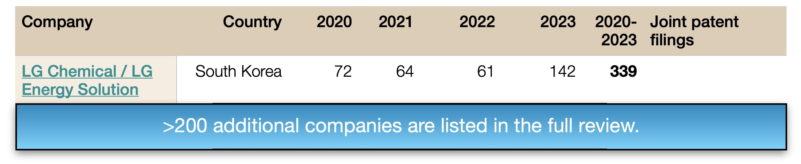
9 new patent families by Amprius have been published since 2022 that are related to high-energy Li-ion battery anodes
(Amprius USA: 2 patent families, Amprius Nanjing & Wuxi: 7 patent families). No lithium metal anode patent families have been published
since 2022.
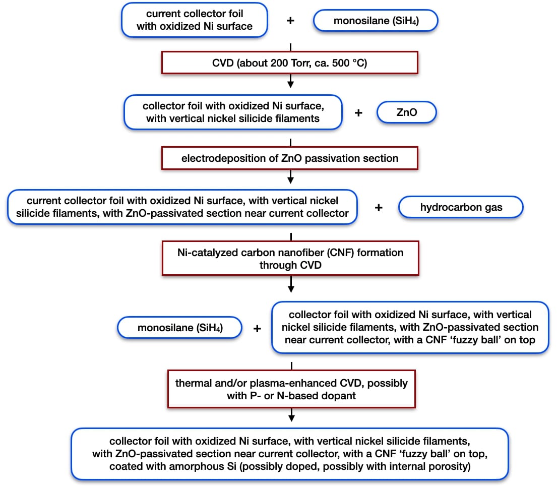
Figure 91: projected next generation manufacturing process option for Amprius (up-scaled implementation may vary)
Example from the patent portfolio
B) Active materials – nano- & microarchitectures, composites; E) negative electrodes for liquid electrolyte cells
-
Process in Figure 91 –
HIGH CAPACITY BATTERY ELECTRODE STRUCTURES
(published in 2022, Amprius USA): orthogonal silicide (presumably nickel silicide) nanowires were first grown
on current collector foil, referring to the patent listed immediately below. Carbon nanofibers (CNF) with ‘fuzzy ball’
shape were grown on top of these silicide nanowires (see Figure 92 – top left), followed by the deposition of amorphous
Si using thermal or plasma-enhanced CVD (see Figure 92 – top right). Very stable electrochemical cycling was obtained in
half-cells with a fist cycle efficiency of >96.5% (Figure 92 – bottom).
It is understandable that very stable cycling in half-cells can be obtained with this approach,
because volume changes during cycling of the silicon nanowires can be very well compensated without crack formation or loss
of electrical contact to the current collector foil.
To also achieve favorable cycling in full cells, the electrode / electrolyte interface area and chemistry will have to
be carefully fine-tuned.
Amprius already has extensive know-how on how to obtain doped anisotropic Si structures with comparably low
electrolyte-electrode interface area (see below).
Presumably, CNF nanofiber-based ‘fuzzy balls’ (380) can be formed on top of the initial template layer (370)
because of the selective presence of catalytically active nickel at the top of nickel silicide filaments.
With this new approach, some of the Si deposition process steps described in earlier patents (see Figure 94)
might be facilitated to achieve process efficiency / cost advantages. Increased Si loading on negative electrodes
might also be feasible (which could lead to increased energy density).
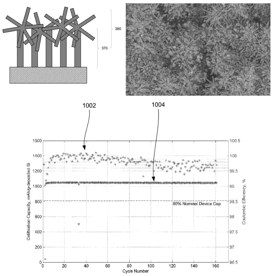
Figure 92: top left – scheme of a current collector foil on which an initial silicide (probably nickel silicide) nanowire template layer (370)
and an additional template layer (380, probably carbon nanofibers) have been deposited; top right – SEM image of an electrode in which
amorphous silicon was deposited on the structure shown on the top left; bottom – corresponding half-cell electrochemical cycling data,
1002: coulombic efficiency, 1004: delithiation capacity (Amprius)
-
Key technical information from prior review edition that remains relevant
-
Possible composition of negative electrodes in current commercial 450 Wh/kg / 1,150 Wh/L liquid electrolyte cells:
- baseball bat-shaped Si columns supported by nickel silicide filaments (Figure 93) on current collector with oxidized Ni surface layer.
- Si columns consist of low density N- or P-doped Si core and high density N- or P-doped Si shell.
- Figure 94 shows the process projection based on the Amprius patent portfolio analysis in the prior review edition.
Key earlier patent that might correspond to up-scaled commercial products
A) Active materials – chemical composition, B) particle nano- & microarchitectures, composites;
E) negative electrodes for liquid electrolyte cells
-
Process in Figure 93 –
TEMPLATE ELECTRODE STRUCTURES FOR DEPOSITING ACTIVE MATERIALS
(published in 2022, Amprius USA, covered in patent update): nickel silicide nanowires
(234 in Figure 93 - top, varying composition along nanowire length: NiSi, Ni2Si, NiSi22)
were formed on a current collector foil with a Ni surface (232, thickness of Ni surface layer:
≥20 nm, oxidation pretreatment of Ni layer with air, 50 Torr, 300 °C, 1 min) through a monosilane
CVD treatment (about 1 volume% monosilane in carrier gas, such as nitrogen, 385-450 °C, about 100 Torr,
about 10 min) using an STS MESC Multiplex CVD system (Surface Technology Systems, UK, used also for the
PECVD step below). Nickel silicide nanowires with up to 20-25 μm length were formed and with about 20 nm thickness.
A zinc oxide passivation section (235) was then electrodeposited, followed by deposition of P-doped Si
active material (236) through PECVD (monosilane SiH4 about 12 volume%, phosphine PH3 about 2 volume%,
carrier gas: helium, about 300 °C, about 1 Torr, radio frequency power: 50 W, about 15 min). As shown
in Figure 93 - bottom, SEM exhibits the unique baseball bat shape of the Si columns (up to 1 μm thickness
at free ends), which is very helpful for cycling stability (low mechanical strain because of thin
connection to current collector).
This work further elaborates several aspects that are crucial for the excellent cell performance at high
energy density that Amprius has reported: 1) use of template (235) to limit Si formation close to the current
collector; 2) oxidation pretreatment of current collector layer, which does not necessarily have to consist
exclusively of nickel, but which should have a ≥20 nm nickel surface layer; 3) use P-doping instead of N-doping
(disclosed in an earlier patent filing).
Figure 93: top: negative electrode structure with passivation section (>235); bottom: corresponding SEM image with
Si columns that are narrow near the substrate interface (Amprius)
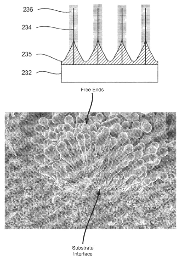
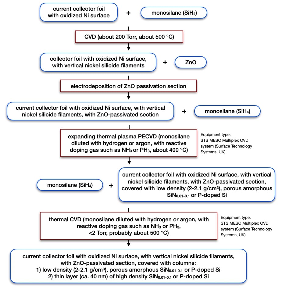
Figure 94: projected current generation manufacturing process option for Amprius (based on patent analysis,
up-scaled implementation may vary)
-
34 additional company assessments are included in the full review.
|